Spiral plate heat exchanger
Spiral plate heat exchanger is a kind of high efficiency heat exchanger equipment, which is suitable for vapor vapor, vapor-liquid, liquid-liquid and liquid-liquid heat transfer. It is suitable for chemical, petroleum, solvent, medicine, food, light industry, textile, metallurgy, steel rolling, coking and other industries. According to the structure, it can be divided into non detachable (type I) spiral plate heat exchanger and detachable (type II, type III) spiral plate heat exchanger.
The spiral plate heat exchanger has been proved to be a kind of high efficiency heat exchange equipment through many years of practice. It is suitable for chemical, petroleum, solvent, medicine, food, light industry, textile, metallurgy, steel rolling, coking and other industries. The heat exchanger is a kind of liquid-liquid and vapor-water heat exchanger, which is designed and manufactured by unique optimization. The structure and process of the product are in accordance with the standard of Sweden "alffaraday" company. The end face of the spiral plate adopts the folded edge argon arc welding, and the special process of "top distance column" is the capacitor storage contactor, which improves the internal and external quality and is recognized by "Baosteel" and can replace the import.
The non detachable spiral plate heat exchanger is designed according to JB / tq724-89 non detachable spiral plate heat exchanger form, basic parameters and dimensions. It has the advantages of simple manufacture, low cost, small volume and good heat transfer performance, but it also has its shortcomings, such as not being able to carry out mechanical cleaning, not easy to repair when it is broken, etc. the selection should be based on the actual project Select specific equipment to make it effective.
Structure and performance
1. This equipment is suitable for: liquid-liquid, gas-gas, gas-liquid convection heat transfer, can be used for steam condensation and liquid evaporation heat transfer, chemical industry, petroleum, medicine, machinery, electric power, light industry and textile and other industrial sectors can choose.
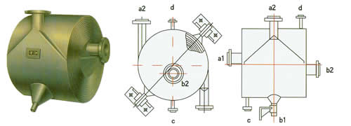
2. The equipment is made of two steel plates, forming two uniform spiral channels, two kinds of heat transfer cut-off, can carry out full countercurrent flow, suitable for small temperature difference heat transfer, easy to recover low-temperature heat source, and can accurately control the outlet temperature.
3. The nozzle on the shell is a tangential structure, with small local resistance, uniform curvature of spiral channel, no large reversal of fluid flow in the equipment, and small total resistance. Therefore, the design flow rate can be increased to have higher heat transfer capacity.
4. The end face of spiral channel is welded and sealed, with good sealing performance and reliable structure.
5. It is not easy to repair, especially when the internal plate is in trouble. Some factories turn off all the welding seams at both ends of the equipment, flatten the plate again, repair welding and then roll it. This consumes too much labor, because it is very important to select spiral plate heat exchanger for anti-corrosion.
6. The production practice has proved that the spiral plate heat exchanger is not easy to be blocked compared with the general tubular heat exchanger, especially the suspended particle impurities such as sediment and small shells are not easy to deposit in the spiral channel. The reasons are analyzed as follows: first, it is the deposition of single channel impurities in the channel, once the turnover flow is formed, it will be washed away; second, the accident is caused by There is no dead angle in the spiral channel, and impurities are easy to be washed out.
7. Because there are spacing columns in the spiral channel to support the channel spacing, no fibrous impurities (cotton yarn, straw sticks, leaves, etc.) are allowed to enter the heat exchanger.
8. Strictly control the outlet temperature of cooling water below the scaling temperature.
9. The commonly used cleaning method is steam blowing or alkali washing. Steam blowing should be directed to the connecting pipe to blow impurities out of the equipment. Many users think this is an effective method.
Detachable spiral plate heat exchanger
The structure and principle of the heat exchanger are basically the same as that of the non detachable heat exchanger, but the channel can be disassembled for cleaning, and the two ends are sealed with heads. It is especially suitable for liquid-liquid exchange with viscous and precipitated liquid, gas-liquid and steam condensation. Because the detachable heat exchanger needs to add head, flange and other components, the equipment cost is slightly higher than that of the non detachable heat exchanger.
Basic parameters
The nominal pressure PN of spiral plate heat exchanger is 0.6, 1, 1.6, 2.5MPa (i.e. the original 6, 10, 16, 25kg / cm2) (refers to the large working pressure of single channel), and the test pressure is 1.25 times of the working pressure.
The material of the contact part between spiral plate heat exchanger and medium is Q235A and q235af carbon steel, SUS321 and SUS304 stainless steel acid steel. Other materials can be selected according to user's requirements.
Allowable working temperature: T = 0 ~ + 350 ℃ for carbon steel, t = - 40 ~ 500 ℃ for stainless steel acid steel, and the range of temperature rise and pressure drop shall be in accordance with relevant regulations of pressure vessel. When selecting this equipment, the fluid in the channel of the equipment should reach turbulent state through proper process calculation. (generally, the liquid flow rate is 1m / sec and the gas flow rate is 10m / sec).
Single equipment can not meet the use requirements, and can be combined with multiple equipment, but the combination must comply with the following requirements: < br / >
Parallel combination, series combination: the distance between equipment and channel is the same. Hybrid combination: one channel in parallel, one channel in series.
Stainless acid resistant steel pn0.6, 1.6Mpa non detachable (type I) spiral plate heat exchanger.
|
Nominal heat exchange area m2
|
Channel spacing mm
|
Calculation
Heat exchange area m2 |
Current Speed
1m/ces Treatment capacity m3/h |
Nominal diameter of nozzle
|
Model
|
Weight(kg)
|
|
|
I 6B
|
I 16B
|
||||||
|
1
|
6 | 1.0 | 3.89 | 40 | I 6,I 16B1-0.2/300-6 | 44 | 50 |
|
2
|
6 | 2.1 | 3.89 | 40 | I 6,I 16B2-0.2/400-6 | 78 | 85 |
|
4
|
6 | 4.4 | 8.2 | 50 | I 6,I 16B4-0.4/400-6 | 131 | 135 |
| 10 | 4.5 | 17.3 | 80 | I 6,I 16B4-0.5/450-10 | 129 | 133 | |
| 10 | 4.8 | 13.7 | 70 | I 6,I 16B4-0.4/500-10 | 161 | 205 | |
|
8
|
6 | 7.3 | 8.21 | 50 | I 6,I 16B8-0.4/500-6 | 212 | 215 |
| 10 | 7.85 | 17.3 | 80 | I 6,I 16B8-0.5/550-10 | 235 | 273 | |
| 10 | 7.3 | 20.90 | 80 | I 6,I 16B8-0.6/500-10 | 237 | 275 | |
|
10
|
6 | 11.1 | 8.21 | 50 | I 6,I 16B10-0.4/600-6 | 295 | 355 |
| 10 | 11.5 | 17.3 | 80 | I 6,I 16B10-0.5/650-10 | 315 | 405 | |
| 10 | 11.2 | 20.90 | 80 | I 6,I 16B10-0.6/600-10 | 305 | 395 | |
|
15
|
6 | 16.9 | 12.54 | 70 | I 6,I 16B15-0.6/600-6 | 415 | 490 |
| 10 | 14.72 | 17.3 | 80 | I 6,I 16B15-0.5/760-10 | 405 | 575 | |
| 10 | 15.0 | 28.1 | 80 | I 6,I 16B15-0.8/600-10 | 400 | 570 | |
| 14 | 15.6 | 39.3 | 100 | I 6,I 16B15-0.8/700-14 | 505 | 680 | |
|
20
|
6 | 21.7 | 8.21 | 50 | I 6,I 16B20-0.4/800-6 | 540 | 710 |
| 10 | 21.0 | 20.90 | 80 | I 6,I 16B20-0.6/800-10 | 555 | 735 | |
| 14 | 20.9 | 39.30 | 100 | I 6,I 16B20-0.8/800-14 | 660 | 830 | |
|
25
|
10 | 26.6 | 29.90 | 80 | I 6,I 16B25-0.6/900-10 | 610 | 950 |
| 14 | 26.9 | 39.20 | 100 | I 6,I 16B25-0.8/900-14 | 720 | 1060 | |
|
30
|
10 | 28.2 | 28.10 | 100 | I 6,I 16B30-0.8/800-14 | 750 | 1180 |
| 14 | 32.2 | 39.20 | 100 | I 6,I 16B30-0.8/1000-14 | 980 | 1370 | |
|
40
|
10 | 45.4 | 35.30 | 100 | I 6,I 16B40-1.0/900-10 | 1130 | 1515 |
| 14 | 40.2 | 19.4 | 125 | I 6,I 16B40-1.0/1000-14 | 1200 | 1630 | |
|
50
|
10 | 53.9 | 35.3 | 100 | I 6,I 16B50-1.0/1000-14 | 1360 | 1755 |
|
60
|
10 | 61.05 | 35.3 | 100 | I 6,I 16B60-1.0/1100-10 | 1920 | 2112 |
| 14 | 60.08 | 49.40 | 125 | I 6,I 16B60-1.0/1200-14 | 2000 | 2200 | |
|
80
|
10 | 81.83 | 35.3 | 100 | I 6,I 16B80-1.0/1200-10 | 2560 | 2816 |
| 14 | 80.9 | 49.40 | 125 | I 6,I 16B80-1.0/1400-14 | 2667 | 1934 | |
|
100
|
10 | 101.9 | 35.3 | 100 | I 6,I 16B100-1.0/1300-10 | 3200 | 3520 |
| 14 | 100.06 | 49.40 | 125 | I 6,I 16B100-1.0/1500-14 | 3333 | 3666 | |
|
120
|
10 | 115.5 | 35.3 | 100 | I 6,I 16B120-1.0/1500-10 | 3870 | 4257 |
| 14 | 119.0 | 49.40 | 125 | I 6,I 16B120-1.0/1700-14 | 4020 | 4422 | |
|
130
|
14 | 128.80 | 49.4 | 125 | I 6,I 16B130-1.0/1750-14 | 4241 | 4665 |
| 18 | 129.09 | 63.5 | 150 | I 6,I 16B130-1.0/1967-18 | 4462 | 4908 | |
|
150
|
14 | 148.1 | 49.4 | 125 | I 6,I 16B150-1.0/1890-14 | 4702 | 5172 |
| 18 | 148.2 | 63.5 | 150 | I 6,I 16B150-1.0/2010-18 | 4962 | 5458 | |
|
Nominal heat exchange area m2
|
Channel spacing mm
|
Calculation of heat exchange area m2
|
Current speed
1m/ces Treatment capacity m3/h |
Nominal diameter of nozzle
|
Model
|
Weight(kg)
|
|
| I 6T | I 16T | ||||||
|
6
|
6 | 6.5 | 8.2 | 50 | I 6, I 16T6-0.4/500-6 | 230 | 280 |
| 10 | 5.8 | 13.7 | 70 | I 6, I 16T6-0.4/600-10 | 285 | 350 | |
|
8
|
6 | 8.7 | 8.2 | 50 | I 6, I 16T8-0.4/600-6 | 370 | 430 |
| 10 | 7.7 | 17.3 | 80 | I 6, I 16T8-0.5/660-10 | 395 | 454 | |
| 10 | 8.7 | 13.7 | 70 | I 6, I 16T8-0.4/700-10 | 405 | 465 | |
|
10
|
6 | 9.9 | 12.5 | 70 | I 6, I 16T10-0.6/500-6 | 335 | 395 |
| 10 | 9.2 | 17.30 | 80 | I 6, I 16T10-0.5/660-10 | 472 | 543 | |
| 10 | 8.8 | 20.9 | 80 | I 6, I 16T10-0.6/600-10 | 410 | 495 | |
|
15
|
6 | 12.5 | 8.2 | 50 | I 6, I 16T15-0.4/700-6 | 510 | 580 |
| 10 | 14.64 | 17.30 | 80 | I 6, I 16T15-0.5/800-10 | 679 | 781 | |
| 10 | 13.3 | 20.9 | 80 | I 6, I 16T15-0.6/700-10 | 575 | 680 | |
| 14 | 13.8 | 29.2 | 100 | I 6, I 16T15-0.6/800-14 | 640 | 755 | |
|
20
|
6 | 19.0 | 12.5 | 70 | I 6, I 16T20-0.6/700-6 | 730 | 845 |
| 10 | 18.3 | 28.1 | 80 | I 6, I 16T20-0.8/800-10 | 735 | 870 | |
| 14 | 18.5 | 39.3 | 100 | I 6, I 16T20-0.8-800-14 | 810 | 960 | |
|
25
|
10 | 23.1 | 28.1 | 100 | I 6, I 16T25-0.8/800-10 | 935 | 1120 |
| 14 | 23.3 | 49.4 | 125 | I 6, I 16T25-1.0/800-14 | 1000 | 1165 | |
|
30
|
10 | 29.0 | 35.3 | 100 | I 6, I 16T30-1.0/800-10 | 1190 | 1470 |
| 14 | 28.1 | 59.4 | 125 | I 6, I 16T30-1.2/800-14 | 1170 | 1425 | |
|
40
|
10 | 40.9 | 20.9 | 80 | I 6, I 16T40-0.6/1200-10 | 1725 | 1885 |
| 14 | 42.3 | 39.3 | 100 | I 6, I 16T40-0.8/1200-14 | 1845 | 2110 | |
| 18 | 44.9 | 63.5 | 150 | I 6, I 16T40-1.0/1200-18 | 2075 | 2405 | |
|
50
|
10 | 46.2 | 35.5 | 100 | I 6, I 16T50-1.0/1000-10 | 1800 | 2085 |
| 14 | 53.2 | 49.4 | 125 | I 6, I 16T50-1.0/1200-14 | 2490 | 2595 | |
| 18 | 54.0 | 76.3 | 150 | I 6, I 16T50-1.2/1200-18 | 2435 | 2820 | |
|
60
|
10 | 56.8 | 20.9 | 80 | I 6, I 16T60-0.6/1400-10 | 2330 | 2635 |
| 14 | 60.7 | 39.3 | 100 | I 6, I 16T60-0.8/1400-14 | 2595 | 2850 | |
| 18 | 59.6 | 63.5 | 150 | I 6, I 16T60-1.0/1400-18 | 2730 | 3150 | |
|
80
|
10 | 76.4 | 28.1 | 100 | I 6, I 16T80-0.8/1400-10 | 2970 | 4060 |
| 14 | 78.6 | 39.3 | 100 | I 6, I 16T80-0.8/1600-14 | 3120 | 3605 | |
| 18 | 82.0 | 63.5 | 150 | I 6, I 16T80-1.0/1600-18 | 3580 | 4205 | |
|
100
|
10 | 101.4 | 28.1 | 100 | I 6, I 16T100-0.8/1600-10 | 3905 | 4330 |
| 14 | 98.8 | 49.4 | 125 | I 6, I 16T100-1.0/1600-14 | 4040 | 4585 | |
| 18 | 98.8 | 76.3 | 150 | I 6, I 16T100-1.2/1600-18 | 4200 | 4930 | |
|
120
|
10 | 115.5 | 42.5 | 125 | I 6, I 16T120-1.2/1400-10 | 4350 | 4980 |
| 14 | 119.0 | 59.4 | 125 | I 6, I 16T120-1.2/1600-14 | 4770 | 5440 | |
|
150
|
14 | 149.15 | 59.4 | 125 | I 6, I 16T150-1.2/1800-14 | 6431 | 7396 |
| 18 | 149.86 | 76.3 | 150 | I 6, I 16T150-1.2/2000-18 | 6643 | 7639 | |
| 20 | 147.6 | 83.81 | 150 | I 6, I 16T150-1.2/2050-20 | 6769 | 7784 | |